

Mad Cat BattleMech
POLYURETHANE RESIN AND PEWTER MODEL KIT
Here are some tips on assembly, painting and care of the Mad Cat model. Please
check out our web page for photos of painted models. If you have questions,
problems, comments, model requests etc. please feel free to write or call.
Enjoy!
MAD CAT ASSEMBLY
OPTIONS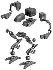
There are many assembly options possible with this model. Be sure to read
Assembly Options section of the instructions and decide which options you
want to use before assembling the model!
The basic buildup was designed for easy assembly with a simple leg pose,
pivoting waist and guns that elevate and rotate.
The first option is building the legs in a more dynamic pose than the basic
buildup gives. With light modification the legs are capable of a wide range
of poses.
The other main option is building the model so the weapons will be
interchangeable. We plan to build up a range of weapons to outfit the OmniMechs
in various configurations as we add more models to the line. For gaming use
we also suggest a number of ways to reinforce the weapon to arm joint.
SUGGESTED PAINTING SEQUENCE
Body: Paint the body either before or after assembly (machine guns
should be painted before assembly).
Legs: Paint ALL of the leg pieces before assembly.
Arms: Paint after assembly except for the missiles which should be
painted before assembly.
BODY
Cockpit (1)
Body Box (1)
Lower Body (1)
Machine Guns* (4)
Laser Pods* (2)
ARMS
Arms (2)
Shoulder Weapon Mount (2)
Missile Launcher (2) Right and Left
Wrist (2) 2 Rights and 2 Lefts
Weapon (2)
Missiles* (30)
Sensor Covers* (2)
LEGS
Pelvis (1)
Hip Cover (2)
Upper Leg (2) Right and Left
Hose* (2)
Lower Leg (2) Right and Left
Heat Sink (2)
Ankle (2)
Foot (2)
* Denotes Metal Parts
CLEAN UP
Your model will look better if you spend some time cleaning up mold lines
with a file or sandpaper and filling the inevitable air bubbles. There are
a couple of spots that need clean up that are easy to miss: webs between
the toe joints, front edge of the lower leg armor, rear edge to the pelvis,
lower rear corners of the body box When filing or sanding, please wear some
kind of dust mask to prevent the urethane dust from getting inside you. It's
not good to eat or breathe.As always, check the fit of the pieces BEFORE
gluing.
BODY
1. Glue the lower body and body box sections together. Gluing rear
box onto the lower hull first allows you to superglue from the inside and
make a strong joint.
2. Slide in and glue the cockpit to the body.
3. Glue the two laser pods to the slots in the side of the cockpit
and the four machine guns into the holes at the front of the cockpit.
LEG AND PELVIS ASSEMBLY
1. Glue the ankles into the feet, before gluing, turn one ankle all
the way clockwise (this is now the left foot). Turn the other ankle all the
way counterclockwise (this is now the right foot). Just remember that the
toes point to the outside.
2. Glue the heat sinks to the backs of the lower legs.
3. Insert the right lower leg into the right foot/ankle assembly and
insert the left lower leg into the left foot/ankle assembly. Don't glue
yet.
4. Attach upper legs to pelvis. The upper legs are labeled at the
knee pivot point with R's and L's for right and left. After checking fit,
go ahead an glue these on.
5. Attach upper legs to lower legs. Don't glue yet.
6. With the leg assembly standing on a flat, level surface and the
pelvis supported from below, put a drop of glue on each joint one at a time.
Check to make sure the feet are flat to the ground and that the top deck
of the pelvis is level.
7. Glue the hip covers to the hips.
8. Glue the longer end of the pewter hose into the hole in the upper
leg and the curved end into the hole in the lower leg.
ARMS
1. File the bottom of the missile launcher flat and check the fit
of the missile launcher to the weapon mounts. Clean up the sprue connection
that might keep the mount from sitting square to the base of the missile
launcher. Making sure that the weapon mount is facing the correct way (the
three facets face to the front, the two facets face to the rear), glue the
missile launchers to the weapon mounts.
2. Glue the pewter sensor cover into the bottom outside corner hole
on each missile launcher.
3. Paint the missile launcher assembly.
4. Glue fifteen missiles into the remaining holes in each missile
launcher.
5. Carefully clean up the wrist pivot point on the arm and on the
wrist joint halves. Check the fit.
Wrist Joint.
Because of the design of the ’Mech, this is not the strongest joint.
If you don't want the weapon joint to move and just want a static model,
you can just glue the piece in whatever position you want it to be in (See
Transport Disassembly though). If you plan on transporting your Mad Cat around
much or gaming with it, you really should reinforce the wrist joint. See
Assembly options for multiple suggestions on wrist joint reinforcement.
Assemble the weapon and wrist joint pieces to the arm (thicker bars on each
joint piece face to the rear) and then glue the wrist joint as described
here. To glue the joints so that they allow the weapons to pivot, put a drop
or two of thin Zap on a piece of scrap and use a wire to pick up very small
droplets of Zap and apply them to the line where the two halves of the wrist
joint touch each other. It's wise to keep move the joint between every drop
or so, to make sure it's not getting stuck in one position.
5. Paint arm/weapon assembly.
FINAL ASSEMBLY
1. Fit the body assembly over the keys on the pelvis and rotate 90
degrees to the front.
2. Slide the missile launcher assembly over the ends of the arms,
and slide the arms into the body/hull assembly. If you did it right, the
missile holes should be pointing forward. If you want to be able to change
out the weapons, do not glue these joints.
Transport Disassembly
To disassemble for transport, remove one (or both) of the arms or rotate
on of the weapons until it clears the legs and remove the body from the leg
assembly. Pack all pieces in bubble wrap separately.
Option: Cockpit
If you want to add an antenna to the cockpit, there is a dimple on the top
where it goes, just behind the canopy. I used 1/32" piano wire cut to about
a half inch. Bend it in the center to about a 45 degree angle. Drill a hole
the appropriate size about 1/8th inch deep roughly perpendicular to the top
surface. Insert the wire and glue, making sure that its level.
Option: Body Box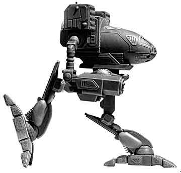
Conversely, if you want the box to be removable to allow for some customization
that might allow bolt-on weapons, a great place to put screws in to hold
the box to the lower hull is in the rear corners of the hull going up into
the rear corners of the box. The screw heads are pretty well hidden there.
Option: Weapons
The weapons have a limit stop at the back to keep them from pointing down.
If you want to make your guns able to depress below horizontal, simply file/sand
the stop off of the gun.
Option: Arms
The arms can be made to rotate forward or backward by removing the key that
locates the arm in the body. If you do this you will have to glue or pin
the missile launcher to the body to prevent it from rotating with the arm.
The arms can be cut and repositioned at any one of the multiple joints. If
you wanted a weapon to fire straight down or something odd, cut the joints,
rotate to the desired position and pin back together.
Option: Feet
In the drawings that this model was based on, the feet do not point straight
ahead, but point a little outward. Other drawings of the Mad Cat show the
feet pointed straight ahead. To assemble the feet with the toes pointed outward
turn the ankle all the way to the right on the right foot and all the way
to the left on the left foot before gluing. To assemble with the feet pointing
straight ahead, align the ankle key at the center of the slot in the foot.
Option: Legs
The kit is designed to be assembled in the pose shown on the box lid, but
is easily modified for a more dynamic poses. For a walking/running pose,
or if you would simply prefer one leg ahead of the other, remove the stops
at the bottom of the upper and lower legs (the 1/4" rods sticking out of
the ends). The key on the pelvis leg joints that keep the upper legs from
pivoting also needs to be removed. Removing these keys allows the leg pieces
to pivot through a wide range of motion. For a an even wider range of motion,
you will have to remove some material from around the pivot points to allow
the legs to swing further. Any modification to the leg pose will require
modification of the pewter hose that attaches to the upper and lower leg
pieces.
The key to assembling the legs in poses other than the standard one is to
keep the pelvis level. I tend to set up one leg the way I like it, then set
up the other leg in contrast to the first.
Shown on the instruction sheet is a Mad Cat at full run. To achieve this
pose the following modifications were made (in addition to the ones described
above): Left leg. Lower heat sink fin was filed down a bit and the lower
leg / upper leg pivot point was cut out in the rear.
Option: Wrist
Joint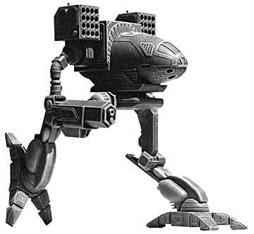
Here are a few ways to reinforce the wrist joint.
a. Drill and pin the joint. Drill through the block at the rear of
the wrist and insert pins with a drop of glue.
b. Staples! You can take a standard desk stapler staple and snip the
prongs to about an eighth inch for the back and a bit under a sixteenth of
an inch for the front. Bend the prongs out a few degrees to match the blocks
and simply glue them onto the blocks to help keep them together.
c. Another method is to take 7/16" outside diameter brass tubing,
cut it to about 1/8" in length (making a ring), and sleeve the joint. Slide
it up onto the arm, assemble the wrist with the gun in place, and then work
the tubing ring down over the wrist joint halves. I have one that I've been
stress testing that was never even glued, and the joint has yet to fail.
d. The easiest method is to use the wire from a twist tie (ie: take
off the paper or plastic and just use the wire). Wrap a twist tie wire loosely
around the cylinder on the arm right above where the wrist joint halves go.
Assemble the two halves with the gun in place. Slip the twist tie wire down
over the round part of the wrist joint halves and tighten with a pair of
needle nose pliers, then glue as normal. Snip off the ends of the wire close,
but leave about one turn.
Battletech models are supplied unpainted. Figures are not provided, they are only shown for scale.